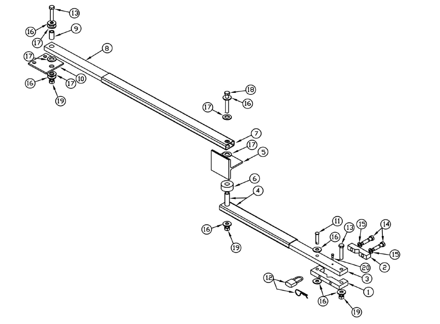
If an obstruction exists to prevent the following mounting refer to string method for nonstandard installation of swing gate operators on page 5.
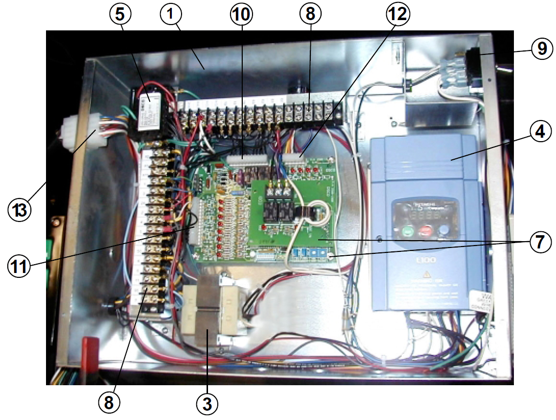
Osco gate operator wiring diagram.
Collection of osco gate operator wiring diagram.
These wire diagrams are for current models only.
Model bgu barrier gates can be used for traffic control and parking applications available in 1 3 and 1 2 horsepower 115v or 230v supply voltage various arm lengths.
Osco model rs instructions page 4 03 04 99 pad mounting note.
Gate operator wiring diagrams.
It reveals the elements of the circuit as simplified shapes and also the power and also signal connections between the gadgets.
Hslg slide gate operator installation guide 2 p1220 revision x10 11 04 2016 wiring specifications refer to the following steps for details on power and.
All gate operators can be divided into one of four different classifications depending on their design and usage.
All osco gate operators are supplied with a power disconnect switch to turn on and off the power supply available to the operator.
Our high quality line of.
Find the listing on this page corresponding to the model voltage and horsepower rating of your operator.
It shows the parts of the circuit as streamlined forms and also the power and also signal links between the devices.
Ac power wiring 1.
Through switch selections the gate operator is universal and suitable for all installation and operational functions.
To be sure you receive the correct wire diagram for your model please have your model and serial number at hand and call our technical support department at 800 421 1587 then press 3 for service.
Osco gate operator manuals all gate operator manuals collection of osco gate operator wiring diagram.
The recommended pad size is 32 x 19 to a depth dependent on local codes or frostline.
The nortek security control family of brands.
A wiring diagram is a simplified conventional photographic depiction of an electric circuit.
Led dip umcb 01 ctrl wiring umcb 01 ctrl.
A wiring diagram is a simplified conventional photographic representation of an electrical circuit.
Keep clear of gate during operation.
Incoming power should be brought into the operator and connected to the labeled pigtails in the disconnect box following wiring specifications on page 4.
Wiring diagram 6103 catalog cut wiring diagrams 6001sl.
Wiring diagram 6103 universal gate board function.
A wiring diagram is a simplified conventional photographic representation of an electrical circuit.


